Six of us at Broadway today to
continue with the southwards march of the point rodding.
A bit of tidying up first to remove the shuttering boxes from the concrete blocks we cast a couple of weeks ago. The ones out in the open are easy to knock off - the ones up against the platform wall need a fair bit of coaxing off. So now all the roller blocks are installed up to the point where we need to cross under the Tracks to platform 1 side.
Just a reminder that although we have three sets of rollers here we only need two runs for the points and FPL with the current track layout. The rodding for a second FPL will only be fitted in the future should an extended loop be required.
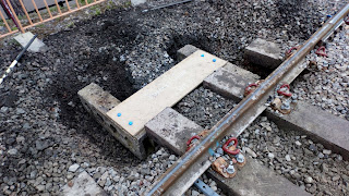
So, now that we have reached the point where we need to cross over, the installation of a pair of concrete blocks is required on which will be mounted the cranks to route the rodding through a right angle So Keith L to the fore with shovel - a mix of roots, soil and ballast here in the shadow of the bracket signal :
You will see from the next picture that we are using a wooden template to line everything up. P Way have adjusted sleeper positions for us so that the two runs of rodding will clear. Note the cranked connecting rod that drops the level to enable access under the rails :
With everything marked in position the template can now be used to mark a steel plate which will be prepared back at base.
Then over to the opposite side to repeat the operation. But hold on, here comes 2807 on its way into the station - our day was interspersed with pauses while we stood and waved at the happy travellers - quite exhausting when you start to realise just how long a slowly moving 8 coach train is!
Another pair of Keith's holes in the ballast with the template set for marking out:
The next challenge is how to get the rodding over Evesham Road Bridge. Malcolm W and John P discussing how to set the roller blocks. A modified bracket and a small mod to the gravel boards may be required.
Meanwhile I have volunteered to make good the brickwork at the bottom of platform 2 ramp. You can see how close the rodding is, there is approx half an inch of vertical clearance underneath.
We will replace the top slabs next time when the mortar has set. Brickwork probably not quite up to BAG standards but fit for purpose!
And finally a view looking back to the signal box of the completed runs of rodding. George had a pull on the two levers in the signal box which slid across smoothly - will require a bit more effort when the points are attached!
Curly


Always an interesting blog! Have I got this straight? The cranks on the P2 side are set to reverse the action - a push is converted to a pull, whereas on the P1 side it repeats the action - push creates a push. I presume this is to get the right operation at the points/FPL?
ReplyDeleteAlso, I was wondering, how does the signalman know that the points have definitely moved? Will you have electrical circuits to indicate position?
Yes, push transfers to pull on platform 2 side and the crank on platform 2 side gives us pull to pull.
DeleteThe points will be protected with a mechanical detection unit. Until the FPL has operated the signal cannot be pulled off.
Thanks for the reply. So where is the mechanical interlock with the signal - at the points?
DeleteMethinks that the interlock with the signal would be in the locking room underneath the signal box. Am I right Curly?
DeleteRegards, Paul.
If the interlock is in the locking room, what happens if the rodding becomes disconnected from the points and they don't actually move?
DeleteThe interlock in the box is between the relevant levers. The point and FPL levers have to be in the correct position for the interlocking to release the signal lever. The FPL won't engage in it's stretcher unless the points are fitting-up properly and if they aren't the FPL lever won't go 'Reverse' in the frame to release the signal lever. Out on the ground there's a detector at the points that ensures that the points and FPL are set correctly before the slide in the signal operating wire is free to pull through it.
ReplyDeleteThanks! I understand a bit better now. Will be looking out for further installation pictures later on!
Delete