Saturday, 30 September 2017

Those wretched resistors

At last we have managed to move some components that were always physically in the wrong place to somewhere where they made more sense.

We have a 2 50 line paxes,  at two signal boxes, these are linked (Tied )by two tie lines in each direction. The book says that  the  line resistance  must be more than 500 ohms so there are these padding resistors; but they were mounted on the side of the Main Distribution Frame and the plan is to update that with a more modern Krone Block. This will give us more reliable access to lines and make mistakes  in tag counting less likely.   But that is still some way off- a job for the winter shutdown.

These resistors were augmented by surge arrestors . These had not operated in the last 20 years since all our cables are buried so I think that they were just Belt and Braces- just in case.  The problem was to understand the Strowger mindset and correctly interpret the diagram.
The notes call for many changes in a tie line circuit that make it very different from a normal " subs'" line so firstly we copied that part of the drawing, then tippexed in all the changes and overlaid it on the original thereby making, in effect, a Tie Line Diagram.

This took a bit of time but was most helpful. The trick then was to find the correct tags on the rear tagstrip and no, the line circuits are not the same numbers as the numbers that you dial, so it needed both Kevern and I to operate the pax by sending a call to the other pax and then seeing which line circuit operated as the call came back again. Eventually, after advising all the Users that the ties may be interrupted for a short period,  we had all the answers. Sixteen jumpers and  an hour with the soldering iron later, and Voila' the mod was done. Like all electrical type work its not very visual . If you do it properly there's no sparks or bangs! but here's a pic of the rear tag block.

 And after testing we left everything working as normal.
When I started this , being used to Post Office drawings I didnt realise the significance  between
  tag - and tag -'. Now I do!
The job of upgrading that original "MDF " into a modern system moves a lot closer.

Thanks for reading and thanks to Kevern for all his help

Mike S

Wednesday, 27 September 2017

Preparing for Pulleys

Tues 26th Sept

Once again off to Broadway today.
We have now taken delivery of four lengths of 9" C-channel which will be used to mount the steel plates which will carry the pulleys and angle cranks coming out of the signal box tunnel --  ALSO a plate is also needed opposite the tunnel at the base of platform 1 to carry the pulleys that will direct the signal wires northwards and to the wooden signal post at the south end of platform 1.
Here we have the channels loaded to deliver to Broadway. Quite substantial lumps - should keep everything rigid !


So, one of our objectives today was to mark out the position for a concrete base along the wall of platform 1 and prepare some shuttering for a concrete block. First of all we dug out the old ballast over a 16 foot length (enough width to cover wires coming from the levers at the ends of the lever frame - and of a width to clear the ends of the sleepers which will appear in the not too distant future).
In doing this now it will avoid us having to dig through another 18" of fresh ballast


Jim P did most of the hard work. Breaking up an shovelling compacted ballast keeps you fit!


We used platform 2 as a workshop to cut up some old 15mm plywood and prepare the shuttering


Then positioned it in the trench.


The height of the  the concrete has been measured from the top surface of the platform allowing for a bit of adjustment when we set the C- channel in the concrete. There will be 4 short lengths of this at right angles to the platform wall on which two steel sheets will be fixed. We hope to do the concreting next week.

Meanwhile down in the bowels of the Locking Room Malcolm and John P have been carrying on with the fitting of the electric locks. Each lock has to be clamped in position to make sure that all the bars and couplings move freely - then mark through the back plate for drilling and bolting.


All 16 are now mounted , but a bit more adjustment and drilling required next week on the last one.


Beginning to look the business but a lot more work still required in the locking trays above (and we haven't even mentioned electrical wiring and cabling yet!)

Curly

Wednesday, 13 September 2017

Block Shelf Stabilisation

Tuesday 12th Sept.

Off to Broadway again - 3 of us plus Andy D who has been slaving away at Toddington machining the couplings to join the tappet blades to the electric lock bars, but more of this later.

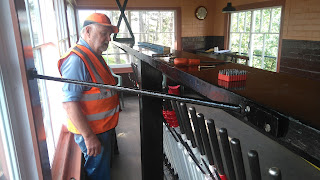
The Block shelf  in the signal box needed additional support to remove its tendency for lateral movement and a central column for vertical support. This central support doubles up as a cable duct to cover the multitude of wires that will eventually feed down from the shelf. Here's the wooden box support which has been assembled and painted since lat week - note that it has a hinged cover to provide access from the window side


Some holes needed in the floor to feed the cabling through, John P in action with a 25 mm dia cutter - 2 holes should suffice - after measuring , a pilot hole tells us that we are missing the joists below


Then into position and adjust for vertical. A couple of screws through the Block shelf  and two into the floor to  secure it into place.


Having now got a pretty sturdy vertical set up we now need a bracket to stop horizontal movement. Here's one we made earlier


This has been attached to the side of the Block shelf and the central window frame and provides a very rigid fixing - it is now impossible to move the shelf in any direction even with a hefty push.


Meanwhile down below in the locking room Malcolm and Andy D were checking the fit of the newly machined couplings and pins to the tappet blades at each position where an electric lock is to be fitted.  


The bars which operate the locks and attach to these couplings  have to be lined up for the coupling holes to be drilled and dowel pins fitted - note that these are then  secured with split pins 


This jigsaw to be continued.

I found a spare  signal wire adjuster before departing for Broadway this morning and took a shot to hopefully give a better view of what one looks like. The central screw has a length of about 2 feet and provides  a significant amount of adjustment. Operated by a removable handle on the top (not shown) which raises or lowers  the looped bar  below. 


Curly

Wednesday, 6 September 2017

More Tension

Tuesday 5th Sept

Four of us at Broadway today to make a bit more progress under the Signal Box in the locking room.
It has been decided to add two more signal wire adjusters to the lines for the Direction Indicator (the most northerly signal at Broadway). This on the face of it was a relatively straightforward job but took us most of the day to sort out.
Upstairs John P fitted the adjuster bodies to the floor. This required a bit of repeated measurement (measure at least twice before cutting and drilling holes!) to ensure that the tails to which the wires attach line up with the  wheels on the levers and to avoid the floor joists.


and here they are eventually poking through underneath .


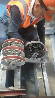
The end of the signal wire will attach to the loop with a shackle. The wire will then pass under a pulley down below and then up and over a second pulley on the lever tail up above. Finally the wire will come down again and pass under a third pulley before going out through the tunnel. The raising or lowering of the adjuster then tightens or slackens the signal wire to compensate for excessive variations in temperature. I think I mentioned in an earlier blog that this mechanism is used for signals further than 300yards from the box- the direction indicator is about this distance away.
So, to complete this installation we need to fit an additional steel plate to the floor channels to mount the additional 3rd pulleys.
We positioned this first to mark out and drill the mounting holes to attach it to the  front C-channel the additional holes required to re-mount the existing rollers had been pre-drilled back at the workshop and matched up well.


Then to  mark out and drill the 3 holes to mount each of the two new pulley assemblies:


And then bolt the whole lot back into place. We just managed to get the nuts onto the bolts without having to  take out the lower "wildlife proofing" board which would have been impossible to get back in with the plate in position.


The next board up needed a small slot cutting for it to sit comfortably over the plate - so now all secure again - job complete until we come to fit the signal wires - more slots needed for these!


While all this was going on Malcolm was continuing with the locking ..........this will continue for a good few weeks yet!

And outside for most of the day  Steve W was going through the platforms with the dumper carrying new ballast up to the north end - should give P-Way a good day's track laying work tomorrow!

Curly