Thursday, 10 February 2022

Toddington Refit

 Tuesday 8th Feb

All hands on deck now to get the new Toddington pointwork reconnected to detectors, signals, rodding, etc. So five of us off there with the diesel railcar trailer loaded for action.


There's quite a lot of work to do here now that the new  pointwork has been re-positioned.

John P and Neil C concentrated on refitting the FPL (lever 11) , stretchers and angle cranks , all of which needed a fair amount of drilling- some through steel and some through sleepers. 


We had taken the precaution of bringing the portable generator with us but we didn't need to use it as there  was , luckily, a mains connection in the adjacent pit and we had a nice long lead to oblige!

Note the multicoloured environment with the brand new yellow  stretchers! Note the insulated joints for track circuiting.


Meanwhile on the platform 2 side there was Malcolm W, John B  and myself dealing with the metal plates for mounting angle cranks onto concrete blocks which have been roughly positioned and need fine tuning to get everything in the right position .


Then followed the problem of getting the point rodding stools (most of which had been removed) back in perfect alignment relative to the track. So, forward with our hightec  equipment -- a large plank (remember the film with Eric Sykes and Tommy Cooper) with attached locating devices! This was very effective.


Getting the alignment of this angle crank to match up in both directions is proving a bit tricky with the mounting plate perilously close to a drain cover.


Most of the  concrete rodding stools that were removed to facilitate the track replacement have to be repositioned with freshly dug  holes in the ballast.


Work will continue with more of our colleagues tomorrow and Thursday . More serious shovelling to look forward to!

Curly

Monday, 7 February 2022

Unlocking the Lock

 Monday 7th Feb

The following is a detailed description of the resolution of a problem with an electric lock from Toddington signal box courtesy of Neil Carr.

For a while now the lever lock on lever 23 at Toddington controlling the point machine for the North siding has been intermittently sticking requiring the cover to be removed, and a brief bit of S & T assistance to the lock mechanism. Often the lock appeared stuck, but then freed when pulled manually  and worked happily once again.

Since the box is currently closed , whilst much point replacement work is happening, the chance was taken to unwire and remove the lock - a Tyers large lock with contract drum. That in itself isn't a five minute job, as there are many connections,  and the lock is well hidden behind the locking trays. These locks have more travel than a standard lock,  having several locking positions   and are driven directly from the lever via an actuating arm  clamped to the lever shaft; therefore they are usually found behind the normal locking and among the signal wires.

The lock was then brought back to the  S & T Coach to be stripped, cleaned and reassembled. 


Given that the lock intermittently jammed up, and then worked for a period once freed  I was expecting to find some dirt or swarf in the mechanism 

 What I actually found  amazed me. At some point in the last few years a signalman must have dropped a plastic pen down through one of the lever slots in the frame; against all odds this had bounced into the back of the lock mechanism and had been comprehensively chewed up by the locking bar moving up and down as the lever was operated. Now and then bits of plastic must have jammed in the lock bolt mechanism  preventing the solenoid from being able to pull the bolt from the lock. 


Whilst the lock was apart the entire mechanism was cleaned of old oil and rubbish ( and pen) the contacts on the contact drum were stripped and cleaned and the lock was set up correctly with the contacts all operating in the correct positions. It was then reassembled clean and dry of oil and grease

This photo gives a good idea of the physical size of these locks, the locking bar is just over a metre long.


Looking right to left we start with the top of the locking bar (they are mounted vertically) where the actuating arm from the lever attaches. Next we have the coli and lock closed connections, then the lock bolt itself , followed by the solenoid coil with the lock actuating arm above it. Energising the coil pulls the iron block at the left hand end of the coil tight to the coil, and via the arm withdrawsthe lock bolt from the locking bar. This locking bar has three positions; as shown it is locked in "Normal"   where the lever is normal in the frame and the points would lie in their normal position.  Underneath the coil you will see a very long slot cut in the bar, when the lock is energized, and the lever moved away from normal the bar is drawn towards the right ((in this picture , in reality it is lifted upeards) until the lock bolt drops into that long slot. The bar then continues its travel until the lefthand end of that long slot hits the lock bolt. The lever is then in the 'Reverse Check' position, and the contact for operating the points reverse is made.

Once the points have moved and been detected in reverse the lock will again energise (automatically via the ele trial locking) and allow the lever to be moved fully reverse  where it will again be locked

Moving from reverse to normal is the same procedure as above , only going the other way. 

The large casting on the left hand end of the lock body is the contact drum. This has a series of pairs of contacts over rotary contact rings, rotated via a gear wheel and a long angled slot in the locking bar. These contacr boxes can have many contact rings and many different lengths and positions of rings - allowing contacts to be made at various positions of the locking bar and for varying durations of its travel. 

An in-depth description of the varying contact combinations is probably touch detail for here, however, suffice it to say.that this contact drum is configured with four contact rings; providing contacts for the Normal, Normal Check, Reverse Check and Reverse lever positions.

The astute of you will however notice that this drum has eight sets of contacts, although only four are used. These locks can have drums which are much longer and can carryall least twice as many contact rings

I hope you found this Informative!


Curly ( on behalf of Neil Carr - S & T Electrical Engineer)

Wednesday, 19 January 2022

Toddington Strip


 Tuesday 18th Jan

In preparation for the replacement of the pointwork at Toddington by contractors (starting this week I believe) we are in the process of removing a whole load of fittings.

So, with four of us plus the Ops Manager we set off in the diesel railcar from Winchcombe with all the necessary tools including a generator to power the large angle grinder for cutting off stubborn/seized nuts. 

It is necessary to:

1. disconnect and remove signal wires and stakes 

2. Remove facing point lock, stretcher bars and all connecting bars and cranks

3. Remove Rodding compensator and mounting plate

4. Remove Point detection unit and mounting plate 

5. Remove Point rodding and cranks 

6. Remove Concrete rodding stools. 

This will allow the whole area of the crossover to be dug out and be re-ballasted/regraded

Getting the FPL out:


At last:


The mounting plate for the compensator having its nuts cut off!


Signal wires cut and removed- just a few short lengths from the bracket signal remaining here


The booty unloaded from the rail car onto platform 2 at Winchcombe ready to take back for cleaning:


We have not attempted to remove the rodding stools yet because they are well secured in dirty ballast. These will be left  for digging out by mechanical means.

There are also a  number of other concrete blocks which will have to be dug out. I'm sure we could manage this with picks and shovels but so much easier with an excavator on site!

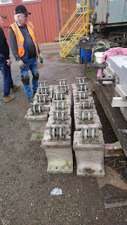
They will be replaced with the ones we removed from the North sidings. These have now had two wheel roller sets fitted. The bolt hole spacings for the older GWR units are a different pitch so the stools have been turned over to suit the fittings with a different hole spacing that you see here:


So plenty of cleaning and bolt sorting to follow. 

Curly

Wednesday, 5 January 2022

Preparation Work at Toddington

 Tuesday 4th Jan

Just two of us plus Malcolm W in today for a visit to Toddington to do some preparatory dismantling ready for some of the major rail replacement work. 

The point motor (for points no. 22) north of the station is planned for removal once all shunting moves have been completed. So to expedite this we have dug out the ballast underneath the sleepers to make spanner access to the bolt heads. (Yes, the dreaded throughbolting!). A liberal coating of release oil has been applied to the nuts so hopefully when we return to unbolt it there will be some yielding!


We then moved further up the track to the North siding which is to have its trap point removed. This means that we need to remove the detection unit and all its connections, about 50 yards of point rodding, a compensator unit, a set of angle cranks and associated linkages to the point motor and finally dig out all the concrete mounting blocks and stools.

Having removed the point rodding Malcolm and John P wrestle out the stools with the aid of a crowbar and brute strength:


The detection unit being disconnected:


A short pause in operations while one of the shunting moves passes with a rake of coaches:


I'm sure that there is going to be a lot more hard graft from many volunteers over the next few weeks. We have to get everything done by the beginning of March!

A happy  New Year to all our followers. 

Curly


Thursday, 16 December 2021

Block Diagram Mounted

 Thursday 16th Dec

Neil C, Malcolm W, Peter W and Andy D went to Broadway Signal Box to lift the completed  illuminated Block Diagram into position. All the wiring and fitting of the LED's has been completed. 

With some well-placed spacing blocks on the block shelf and a T-shaped prop stood on the block shelf the job of manoeuvring this heavy object into position went very smoothly. 

I hope you agree that this looks good and makes a nice addition to the box. 

The diagram has been wired up internally and tested and now just requires linking to the block shelf mounted connector. 

Thanks go to Robin Walker and Kevin Simpson for their assistance in designing and drawing the diagram layout. 


Malcolm, Peter and Andy posing by the diagram! 


And a front view


Curly


(Photos courtesy of Neil C) 

Thursday, 2 December 2021

Bonding

 Wednesday 1st Dec

Some re-bonding of replacement rails at Broadway Station was carried out by Neil C, Carl S and Keith L today. 

Carl and Keith inserting bonding wire adjacent to platform 2. (photo courtesy of Neil C


Curly

Wednesday, 1 December 2021

Unfinished Business

 Tuesday 30th Nov

We set off to CRC again today to complete the salvage of the spare point rodding rollers and brackets from the concrete stools heading north from the signal box. Quite a few seized nuts which wouldn't yield to spannering so we resorted to splitting them with an angle grinder. We ended up with quite a pile


We plan to use these at Toddington when the pointwork and rodding is replaced in January.

The rest of the day was spent back at Winchcombe putting the rollers, brackets, spacers and rods into sets 


And cleaning and oiling the salvaged bolts. 


Curly